Introduction
Recently, we got a lot of requests from fellow designers to show or explain how to create a really cool product presentation for interfaces. Individual explanation of all the nuances can take quite long time, so we decided to share our experience and demonstrate detailed instructions in this tutorial.

Surely, most of you have seen something similar on various websites or platforms. But you might ask why these elements are being implemented nowadays? In most cases, the reason may be a desire to create a spectacular presentation: either to impress customers or to entertain and impress the other designers. They also can often be shown directly to the audience of your new product in a commercial. In general, our tutorial is useful to anyone who is somehow connected with digital design or marketing.
Processing
To work with 3D mockups we’ll need Cinema 4D and Adobe After Effects (AE) programs.
Cinema 4D is a universal integrated program for creating and editing three-dimensional effects and objects. It allows you to render objects using the Guro method. Also, it provides support for animation and high-quality rendering, has a simpler interface than other similar programs, and includes a built-in support for the Russian language which makes it popular among Russian-speaking users.
Adobe After Effects is Adobe Systems software for video editing and dynamic image creation. The program provides a possibility to develop a composition (compositing), create animations and various effects. It’s widely used for footage processing – color correction and post-production. With this tool you may create commercials, music videos, produce animations for television and web, design and animate titles for feature films and television films, and overall use it for a number of other tasks that require the use of digital video effects.
It’s important to admit, for implementation of all the mentioned features you don’t necessarily need Adobe After Effects, any video editing software that you like can be applicable.
Cinema 4D. Introduction
After you have installed the program on your computer and launched it, you’ll see the start screen. There you might find several puzzling things, but don’t get concerned, everything has its own order, so you’ll understand all the tools intuitively.

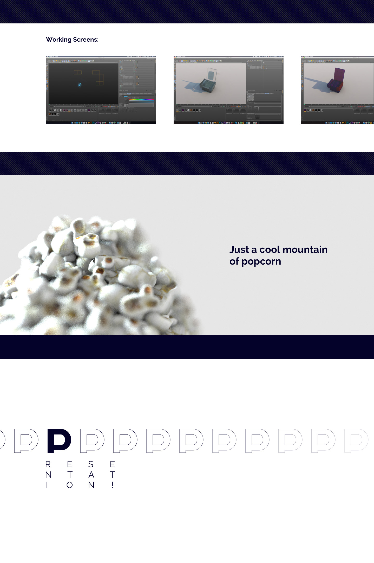
The panel you see in the image above is used to create various 3D objects. It’s effective for creation of the environment or the dynamics in the video.
The objects in this menu are parametric objects (primitives), i.e. they are created on the basis of mathematical formulae using a number of preset values. A significance of this is that such an object is initially a mathematical abstraction and is not editable. In plain language, this means that primitives have no points or surfaces that you can interact with.

Pay attention to the render selection panel. With this option you can run a normal render, a sequence of renders, or send a render to a remote server from it.
When you open the panel, on the right side there you’ll find a window of any object parametres, as well as project settings (Attribute Manager), objects, or tags.
The Attribute Manager gives you quick access to almost every parameter in Cinema 4D, including the parameters of objects, tools, tags, materials, etc. In addition, you can animate directly in the Attribute Manager without opening the Timeline. You can animate all parameters that have a circle icon next to their name.
Changes made in the Attribute Manager are carried out in real-time in the relevant windows.
Animations can be created by using one of the following methods:
Keyframing together with the Record Function;
Auto-keying;
Creating keys in the Attributes Manager;
Creating keys and tracks manually in the Timeline.
All this is quite intuitive, and if you have ever worked with some animation editors, you will immediately understand the flow. Well, if not, you can follow the instructions in this article, and you’ll be able to create a decent animation till the end of reading this tutorial.
To start with this option double-click on the window, or click on the buttons ‘Create’ and then ‘Create Material’.
You’ll find the panel with tools for selection of the objects, as well as options for changing the plane (polygon) mappings and snapping the objects. In most cases you will not need it. We recommend another useful method of polygon selection which is represented on the panel with an icon of the cube with one tinted edge.
Working with Objects
It can seem to be expensive and complicated to model a phone mockup, so if you want to save your resources, use free3d.com. There you will find any model you need. In our case, it will be an iPhone X, so we download this file with a 3D model.
Open the downloaded file in Cinema 4D. You will see something similar to this on your screen:
Then, you have to delete the extra files in the objects window, leaving only the phone model. In this case, the object is called “i phone x.1”.
And here comes a very important moment, many of the objects that you find, will have pre-installed materials. They need being deleted. In Cinema 4D, the materials on objects are displayed on the icon of a sphere to the right of the object name.
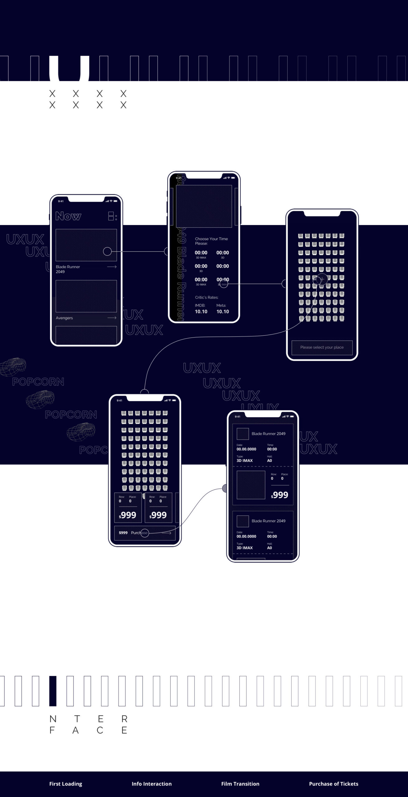
Groups of objects will be displayed if you press a Plus icon to the left of the name of the file. Since the phone 3D model is a rather complicated construction, it will have many components. Open the group by clicking the left mouse button on the Plus icon. It lets us see a great deal of information which can seem to you as garbage. All this is not necessary for our purpose, but we will leave it in the initial state for the beauty and integrity of our future mockup. The only thing that needs to be changed is to delete all materials with a Question Mark icon.
To reach a required result, we need only the last object (phone shell). It’s called ‘frame mobile.1-Buttons’. Many models that you find on the Internet have preset polygon highlights. In Cinema 4D, they are displayed with orange triangles. In order to activate them, you need to double-click on each with the left mouse button.

Activate the saved segment of the polygons and you’ll observe a similar picture.

In the future we will put here the material with the texture of the phone interface.
If there is no blank space on the model, you will have to select the screen manually using the polygon selection tool.
Next, we analyze the possibility of changing the position in space, as well as changing the size of an object. So, the first function is Movement (key “E”). With its help you can move an object in three planes (surfaces): X, Y, Z.
Just a few tips:
Clicking and dragging on the axes lets you move the object along the axes.
Press Shift and Ctrl/Cmd keys for the Move tool.
Pressing the Shift key does the following:
If pressed prior to clicking on an axis, the movement will take place on a plane vertical to the axis.
If pressed after you have started moving the object, the movement will be quantized, i.e., in steps of 10.
If pressed without touching the axis, the movement will be restricted to the axis that lies the nearest to the mouse movement when the mouse button is pressed.

The second function is Resizing the Object (T key), also in three planes: X, Y, Z.
And the last operation is to Rotate (R key). With a help of this tool you can change positions of the surfaces. The next stage is texturing.
Remember, in order to create a material, you need to double click in the bottom left of the screen. In this case, we will have a standard material.

Then, click on the emerged area of the material and see the window with a bunch of settings. At this stage, we’ll need only the item “Color” on the left and the item “Texture” on the right.
But, anyway, the Material Editor is divided into panes. A preview of the material is displayed in the top left corner. There are also numerous pages of parameters, the settings of which are combined to form the material. You will find a list of these parameter pages — known as channels — in the left section of the dialog window (or in the Attribute Manager’s Basic tab).
Predominantly, you will not need to use all the channels. Use the option boxes next to the channel names to choose what channels (i.e. properties) are used as the material. To access a parameter page, click the desired name of the channel or on the corresponding tab. Each page operates in a similar way and the control elements are arranged in the same way.
Properties and what they control:
Color | Stands for a surface color |
Diffusion | Provides irregularities in the surface color (used for brightening and darkening the color channel) |
Luminance | Adds luminescent color (light-independent color) |
Transparency | Transfers transparency, including the refraction index |
Reflectance | Provides the ability to reflect other objects/specular highlights |
Environment | Provides environment reflections (simulates reflections) |
Fog | Transfers the fog effect |
Bump | Creates virtual bumps on a surface |
Normal | Generates virtual surface irregularity that is lit realistically |
Alpha | Provides localized texture invisibility |
Glow | Creates the glowing halo around objects |
Displacement | Generates realistic bumps on a surface |
Editor | Stands as a material display in the Viewport |
Illumination | Creates global illumination, caustics, illumination model |
Assignment | Is a list of all objects that use the material |

Now, we click on the large wide button to the right of the texture and select the interface, be it video or image. There we agree to transfer the file to the project folder and wait for loading. After downloading, click the file name that appears.

As a result, we’ll see this menu:

When our interface has already been downloaded, you can go to the “Animation” section and see, for example, how many frames the video takes. In the drop-down list called “Mode” you can choose how the animation will play out. There are three options available “Normal”, “Mirror” and “Repeating”.

You can try playing with the Luminance tab. The settings there can be used to display the screen brightness, or, for example, to simulate turning-on/off.

Next, go to the tab “Reflectance”, it stands for the reflection on the surface of the object, that provides some glare of light, or just the usual reflection of the screen in the turned-off state.

The Glow effect is responsible for the amount of the glow of the texture. It is not a standard parameter, so you don’t need to use it, but if you still decide to, be careful, it is easy to overuse it.

Our next step is optional, but it can facilitate your work. Go to the “Editor” tab and tick the “Animate Preview”. Now our interface animation will play in the workspace.

At this point, our material is ready and we can put it on polygons. To do this, we choose the saved selection (orange triangle on the object) and drag the material from the bottom left corner to the object.

The texture may not be reflected in the model correctly, so we’ll need to customize it. To open the settings tab, click once on the sphere of material, the one which is applied to the object itself, the settings tab for the material overlay opens below the menu.

To correct the situation (it is often a mirror image of the material), we shift one of the width or height parameters into a minus state. Here you can simply correct the display itself. For example, Length U is the width, Length V is the height, Offset U and Offset V stand for the display of the texture on our object.
Work with Camera
In the upper part of the program screen there is an icon of the camera. In fact, the use of a standard camera will be enough for us.
So, in order to move the camera, open all the working spaces and freely move the camera as you need. In order to animate it, put the necessary keys on the timeline.

After completion, go to the settings section. We tick the two lower parameters and set them so that the object is on the center line of the lens – this will give us a blur effect near and far backgrounds.
Just a short explanation:
The Depth Range is a measure of the depth to which a difference in depth should be darkened. This can be seen in the image above in which an occlusion was calculated in the marked areas on the left, even though the structure is not touching the surface below it.
The Depth Range at this location is so great that the distance between the surface and the structure’s edge lies within this value. On the right, with the smaller Depth Range value, the value is less than the distance between the two objects.

Actually, it should look something like this:

Render Settings
Great, almost everything is ready! All that is left to do is to set up and run the render.
To do this, click on the Render settings icon:

There we’ll see the opened window in which we immediately set our output file resolution, the number of frames per second, as well as the total number of frames.

Go to the “Save” tab, where we set the save path as well as the file extension type.

Click on the Effects tab and add three parameters “Ambient Occlusion”, “Global Illumination” and “Depth of Field”:

In the section “Depth of Field” you can change the settings of the blur.

Expose the camera by clicking on the black box icon.

We launch our render by clicking the central icon in the top panel:

We see a window that appears, if you did everything correctly and clearly followed the instructions, we will have a wonderful video file.

In case you decide to create several cameras and render them one by one, you can combine all the received files in any video editor, for example, Adobe After Effects:

Completion
Well, even though our lesson turned out to be quite extensive, I hope the one who read this to the end can realize that there is nothing complicated. Moreover, after being guided by the principles outlined in this article, you can create absolutely anything. Yes, even PIXAR-like animated movies.
Thank you for your attention.
Subscribe to our blog and good luck with your projects.
P.S. You can also find some useful stuff about 3D here: https://help.maxon.net/us/#1000


